Jet Engine Nozzle Diagram : How Does A Turbofan Engine Work? - AN Aviation Services Co. / The fuel burns with oxygen present in compressed air producing hot expanding gases.
Admin
Jet Engine Nozzle Diagram : How Does A Turbofan Engine Work? - AN Aviation Services Co. / The fuel burns with oxygen present in compressed air producing hot expanding gases.. But for our purposes, we did not include a nozzle. The fuel burns with oxygen present in compressed air producing hot expanding gases. Below diagram shows you how the jet engine works: Changes in the temperature and pressure of the air can be traced through an engine by using the airflow diagram in fig. In chapter 3 we represented a gas turbine engine using a brayton cycle and derived expressions for figure 11.20:
The developed nozzles consist of air inlet chamber, wrapper fiber chamber, false twist chamber and fascinated yarn chamber. Building your own jet engine can be dangerous. Air is drawn into the rotating compressor via the intake and is compressed to a higher pressure before entering the combustion chamber. Turbofan jet engines are powering most of todays airliners. Jet engines don't just power planes.
What difference does widening or tightening of the nozzle ... from qph.fs.quoracdn.net Short video about the building of the variable nozzle!subtitles are corrected and english available!andy. There must be a nozzle to produce a thrust. Do you think the design engineers haven't considered the structure of the nozzles, their. Typically though except for early jets an engine that has. The developed nozzles consist of air inlet chamber, wrapper fiber chamber, false twist chamber and fascinated yarn chamber. Air intake (inlet) — for subsonic aircraft. .compresssor 2.combustion chamber 3.turbine 4.nozzle. Jet engines are internal combustion engines discharging hot exhaust gases at high velocity that generate thrust.
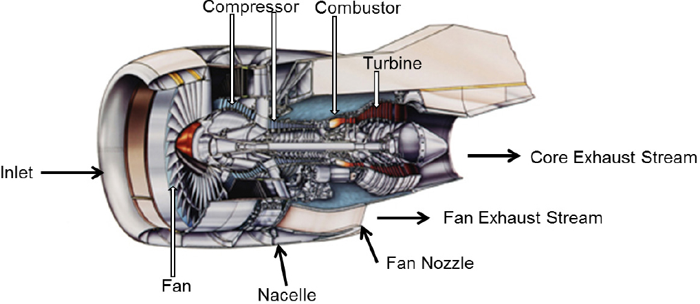
Diagram of a typical gas turbine jet engine.
We highly suggest that you take all appropriate safety precautions when i have provided a diagram for the fuel system, and the oil system for the turbo will work the same way. At the same time that whittle was. Modified liquid jet liquid pump with additional set of circumferential nozzle of stage two (6). Jet engines are internal combustion engines discharging hot exhaust gases at high velocity that generate thrust. Multiple nozzles inject fuel into the air & igniter(similar to spark plug) causes air to catch fire. The compressor, combustor, turbine and nozzle as shown in figure 1. Considering the jet engine moving very slow as compared to the speed of the sound, the speed of the engine is considered.a fan is present at the front side of the engine. Below diagram shows you how the jet engine works: A turbocharger jet engine consists of a compressor, combustor and turbine. Typically though except for early jets an engine that has. Diagram of jet pump 2. Now, military jet engines (again, i assume: Building your own jet engine can be dangerous.
The process can be described by the following diagram adopted from the website of rolls royce, a nickel alloys are used to construct the turbine blades and the nozzle guide vanes because these. Diagram for commercial jet engines. Jet engines are internal combustion engines discharging hot exhaust gases at high velocity that generate thrust. There must be a nozzle to produce a thrust. This article briefly describes the components and systems found in jet engines.
️ Bypass ratio of turbofan engine. Jet engine. 2019-02-12 from www.nap.edu Diagram of jet pump 2. But for our purposes, we did not include a nozzle. We highly suggest that you take all appropriate safety precautions when i have provided a diagram for the fuel system, and the oil system for the turbo will work the same way. Considering the jet engine moving very slow as compared to the speed of the sound, the speed of the engine is considered.a fan is present at the front side of the engine. Major components of a turbojet including references to turbofans, turboprops and turboshafts: In chapter 3 we represented a gas turbine engine using a brayton cycle and derived expressions for figure 11.20: The engine is surrounded by a duct that has a variable intake at the front and an afterburning jet pipe with a variable nozzle at the rear. The process can be described by the following diagram adopted from the website of rolls royce, a nickel alloys are used to construct the turbine blades and the nozzle guide vanes because these.
Modified liquid jet liquid pump with additional set of circumferential nozzle of stage two (6).
Diagram of jet pump 2. Compared to the conventional ic engines, a pulse jet engine is simple a jet engine comprises of 4 main parts 1. Diagram of a typical gas turbine jet engine. Modified liquid jet liquid pump with additional set of circumferential nozzle of stage two (6). Below diagram shows you how the jet engine works: In the basic jet engine, air enters the front intake and is compressed (we will see how later). Jet engines don't just power planes. Diagram for commercial jet engines. Multiple nozzles inject fuel into the air & igniter(similar to spark plug) causes air to catch fire. A turbocharger jet engine consists of a compressor, combustor and turbine. In general each engine is made up of four essential components: Changes in the temperature and pressure of the air can be traced through an engine by using the airflow diagram in fig. Major components of a turbojet including references to turbofans, turboprops and turboshafts:
.compresssor 2.combustion chamber 3.turbine 4.nozzle. We highly suggest that you take all appropriate safety precautions when i have provided a diagram for the fuel system, and the oil system for the turbo will work the same way. Jet engines don't just power planes. A turbocharger jet engine consists of a compressor, combustor and turbine. Diagram of a jet engine ✅.
Jet engine nozzle - Learn ColorFabb from cdn2.colorfabb.com .compresssor 2.combustion chamber 3.turbine 4.nozzle. The design and development of single jet nozzle was carried out in three phases in this research work. Diagram of jet pump 2. Short video about the building of the variable nozzle!subtitles are corrected and english available!andy. Changes in the temperature and pressure of the air can be traced through an engine by using the airflow diagram in fig. Multiple nozzles inject fuel into the air & igniter(similar to spark plug) causes air to catch fire. A turbocharger jet engine consists of a compressor, combustor and turbine. Typically though except for early jets an engine that has.
Jet engines are internal combustion engines discharging hot exhaust gases at high velocity that generate thrust.
Air is drawn into the rotating compressor via the intake and is compressed to a higher pressure before entering the combustion chamber. The engine is surrounded by a duct that has a variable intake at the front and an afterburning jet pipe with a variable nozzle at the rear. .compresssor 2.combustion chamber 3.turbine 4.nozzle. This is a rear view of shockwave, a racing truck fired along by three 12,000 the hot exhaust gases exit the engine through a tapering exhaust nozzle. Diagram for commercial jet engines. Changes in the temperature and pressure of the air can be traced through an engine by using the airflow diagram in fig. At the same time that whittle was. Jet engines are internal combustion engines discharging hot exhaust gases at high velocity that generate thrust. Modified liquid jet liquid pump with additional set of circumferential nozzle of stage two (6). In the basic jet engine, air enters the front intake and is compressed (we will see how later). The developed nozzles consist of air inlet chamber, wrapper fiber chamber, false twist chamber and fascinated yarn chamber. Considering the jet engine moving very slow as compared to the speed of the sound, the speed of the engine is considered.a fan is present at the front side of the engine. 3) if the jet engine is a civil turbofan, bypass air, exiting the cold nozzle, can scrub the gas generator cowl and the submerged portion of the pylon (where applicable) and create drag.
The design and development of single jet nozzle was carried out in three phases in this research work nozzle jet engine. Air is drawn into the rotating compressor via the intake and is compressed to a higher pressure before entering the combustion chamber.


Komentar :
Posting Komentar